
Abstract
Rechargeable seawater batteries (SWBs) use Na+ ions dissolved in water (seawater or salt-water) as the cathode material. They are attracting attention for marine applications such as light buoys, marine drones, auxiliary power for sailing boats and so on. So far, SWB design has been developed from the coin-type to prismatic-shape cell for research purposes to investigate cell components and electrochemical behaviors. However, for commercial applications, that generally require >12 V and >15 W, the development of an SWB module is required, including cell assembly and packing design. The purpose of this work was to conduct research on the SWB cell assembly method while considering the SWB's properties and minimizing current imbalance. Additionally, a 5 Series (S) 4 Parallel (P) SWB module is constructed and validated using commercially available light buoys (12 V, 15 W).
Export citation and abstract BibTeX RIS

This is an open access article distributed under the terms of the Creative Commons Attribution 4.0 License (CC BY, http://creativecommons.org/licenses/by/4.0/), which permits unrestricted reuse of the work in any medium, provided the original work is properly cited.
As demand for renewable energy continues to grow, energy storage systems (ESSs) is attracting attention. 1 Recently, the utilization of ESSs in the marine environment has been considered in the point of the possibility for greater energy efficiency from offshore renewable energy. 2,3 Currently, the most widely used rechargeable batteries are lead-acid batteries (LABs) and lithium-ion batteries (LIBs) 4–7 However, their use in marine environments has been hindered by a decreased cycle life caused by seawater flooding and corrosion. To avoid flooding issues, batteries must be completely sealed, but LABs require vents to release gas generation and LIBs have possibility of thermal runaway. 8,9
As a candidate for marine envrionment batteries, rechargeable seawater batteries(SWBs) are attracting attention. SWBs use Na+ ions dissolved in water (seawater or saltwater) as the cathode material. 10 The use of seawater as an cathode material or as an electrolyte is currently being researched. Because these SWBs are operated while immerged in seawater, there are no issues with flooding. Additionally, a safe environment is maintained throughout operation due to the absence of hazardous components and the absence of an explosion risk. So far, SWBs have been developed from coin cells to prismatic cell 11,12 (Fig. 1a); although these studies contributed greatly to the development of materials and platforms suitable for operating in seawater, the unit cell performance only reached 2.6 V and 2 W, which means they have limited applications. Therefore, research on SWB module with series and parallel connection is required for applications which have high operating voltage and high-power driving conditions (Fig. 1a).
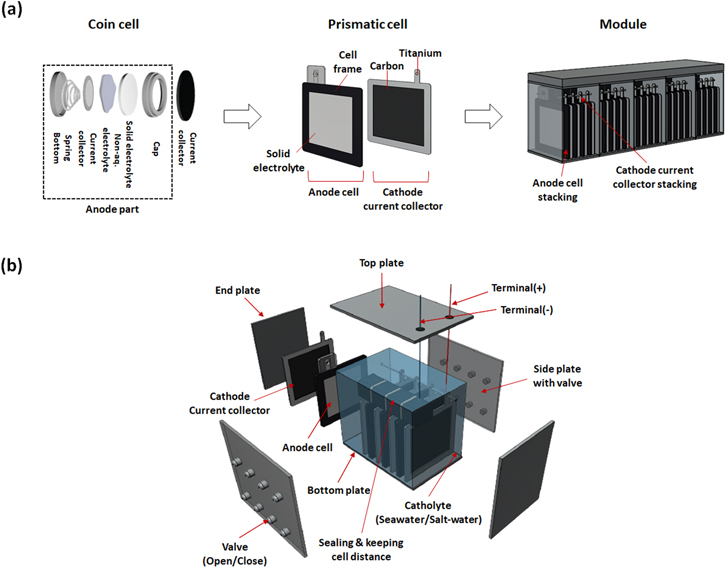
Figure 1. (a) Development of seawater battery from cell to module, (b) Exploded view of seawater battery module.
Download figure:
Standard image High-resolution imageThe objective of the battery system, which consists of a module and a circuit, is to be compact and lightweight while ensuring that all cells perform evenly. When a module is developed without considering cell deviations, performance characteristics such as energy, power, and cycle life could decrease. 13–16 To minimize cell deviation, it is required to maintain (1) cell manufacturing consistency, (2) cell assembly uniformity, and (3) module operating environment control. 17 To begin, non-uniformity in cell production refers to the fact that the cells produced have varying internal resistance or initially capacity as a result of impurities or material ratio variations. Cell variation caused by these non-uniformities is mitigated by the battery sorting process, which groups batteries with similar performance. 18 Second, cell assembly entails electrically connecting cells and physically securing them against the external environment. A difference in contact resistance may occur during the electrical connection of cells. To minimize this, it is vital to choose an assembly method that is appropriate for the battery system from among the different electrical connection methods available, such as ultrasonic welding, spot welding, press contact and so on. The third is a parameter variable that occurs during the operation of the battery module. For instance, while charging and discharging of LIBs, the heat generated causes variations in the stacked cells. 19 These variables are regulated by adding a cooling system 20 or circuit technology, such as a battery thermal management system, 21 into the module case.
Specifically, due to the fact that the anode cells share a cathode, the SWB module should address the following three points (Fig. 1b). The first is the method of assembly. When assembling the anode cell, connectors must be waterproof to avoid contact with the cathode. When assembling the cathode current collector, it is critical to consider the cathode current collector's placement on the battery module due to the fact that this determines the current distribution among stacked cells. The second is the design of the module's housing for series connection. Due to the shared cathode characteristic of SWBs, all cells are connected in parallel. However, a series connection is required for driving applications requiring a high operating voltage, prompting the use of a module case designed for series connection. The third component is the design that considers parameter variations during operation. Several parameters change during the operation of SWBs, including salinity, flow rate, dissolved oxygen (DO), acidity, and temperature. Cell deviation may occur if each cell in a module is exposed to a locally distinct environment. As a result, it is required to analyze the influence of each parameter variation and to define the module design and circuit technology requirements necessary to respond to them.
The aim of the research is to develop a method for assembling cells suited for SWB systems and to develop a module case for series connection. To establish the degree of performance increase in the module, a 5 Series (S) 4 Parallel (P) module is manufactured and the improvement in power and energy is measured. Additionally, the tests conducted under light buoy driving conditions demonstrate the SWBs' suitability for marine applications. This type of research could serve as a foundation for future module research in areas such as cell deviation analysis, circuit design for SWB, and SWB modules with high energy and power density.
Experimental
SWB cell preparation
For anode cell, it has a size of 136 (L) × 6.3 (T) × 170 mm (H) and is designed to have a maximum unit cell capacity of 33.85 Ah depending on the type of anode active material. 2 M Sodium, 0.1 M biphenyl (Thermo Fisher Scientific Inc., NaBP, Republic of Korea) + 0.1 M Sodium hexafluorophosphate (Thermo Fisher Scientific Inc., NaPF6, Republic of Korea) + Hard Carbon Powder (AEKYUNG PETROCHEMICAL CO.,LTD., HCP, Republic of Korea) in Di-Methyl Ether (DAEJUNG CHEMICALS & METALS CO., LTD., DME, Republic of Korea) were mixed as a semi-solid anolyte. 22 For 4.5 L, biphenyl 1190 g, NaPF6 64 g, DME 1943 g, HCP (as an active material) 1543 g, and sodium metal (as a salt for electrolyte) 177 g were mixed and stirred for one day using an agitator in a glove box. The semi-solid anolyte had 1.1 g ml−1 and 42 S cm−1 at 26 °C. The anode material used in this experiment was manufactured on a 4 L scale. A Stainless Use Steel (SUS) mesh was used as an anode current collector with a size of 95 × 95 mm and Na3.1Zr1.55Si2.3P0.7O11 (vA-NASICON) with an area of 100 × 100 mm, a thickness of 1 mm, and a conductivity of 1.0 × 10⁻³ S cm−1 as a solid electrolyte were used. NASICON was prepared by spray drying and a solid-state reaction. The cell manufacturing process is illustrated in Fig. S1 (available online at stacks.iop.org/JES/169/040508/mmedia). First, on one side of the polypropylene frame, NASICON was combined using an adhesive film and a laminated film using a heat-sealing method. This was repeated for the opposite side of the frame and 30 ml of semi-solid anolyte was injected into the anode cell platform. After closing the injection hole with a polypropylene material stopper, it was heat-sealed. For the cathode part, as a cathode current collector, carbon fiber (HYUNDAI FIBER CO., Ltd., C120–3K, Republic of Korea) and a titanium plate (TSM-Tech Co., Ltd., Republic of Korea, 0.1 (T), Gr.2) were used. Carbon fiber with an area of 936 cm2 per unit cell was used. After the Carbon fiber was folded to 170 × 130 mm, titanium plates were placed on both sides and spot-welded. As a catholyte, sodium ferrocyanide decahydrate (Thermo Fisher Scientific Inc., Republic of Korea) was dissolved in natural seawater (Ilsan beach, Ulsan, Republic of Korea (GPS: 35.497005, 129.430996) without filtration). The catholyte solution was used as a 0.4 M solution by dissolving 193.6 g of sodium ferrocyanide per 1 l of seawater.
SWB cell sorting and assembly
Before stacking the anode cells, the resistance of all the cells was measured using a battery impedance meter YR1030 + (Hangzhou Yaorui Co., Ltd., China). The resistance of the full cell was measured using a Carbon fiber with an area of 936 cm2 in a 215 ml catholyte solution, and cells with deviations of less than 5% (average internal resistance: 0.94 Ω) were used for module manufacturing (see Table I). The cathode current collector was modularized by connecting carbon fibers with an area of 936 cm2 with a titanium plate, and a total of 18720 cm2 of carbon fibers were used in the 5S 4P configuration module.
Table I. Individual cell voltage and resistance and contact resistance that occurs when configuring 5S 4P modules.
| 5 Series connection | Cell number | OCV (V) | Cell resistance (Ω) | 4 Parallel resistance (Ω) (Experimental) | Contact resistance (Ω) |
|---|---|---|---|---|---|
| 1 | 1 | 2.84 | 0.972 | 0.357 | 0.119 |
| 2 | 2.84 | 0.959 | |||
| 3 | 2.84 | 0.953 | |||
| 4 | 2.83 | 0.922 | |||
| 2 | 5 | 2.84 | 0.907 | 0.345 | 0.114 |
| 6 | 2.84 | 0.914 | |||
| 7 | 2.84 | 0.894 | |||
| 8 | 2.84 | 0.987 | |||
| 3 | 9 | 2.84 | 0.906 | 0.358 | 0.124 |
| 10 | 2.84 | 0.935 | |||
| 11 | 2.84 | 0.97 | |||
| 12 | 2.84 | 0.934 | |||
| 4 | 13 | 2.84 | 0.942 | 0.351 | 0.121 |
| 14 | 2.84 | 0.894 | |||
| 15 | 2.84 | 0.914 | |||
| 16 | 2.84 | 0.924 | |||
| 5 | 17 | 2.83 | 0.954 | 0.339 | 0.098 |
| 18 | 2.83 | 0.967 | |||
| 19 | 2.84 | 0.976 | |||
| 20 | 2.84 | 0.962 | |||
| Total | — | 1.750 | 0.577 | ||
Electrochemical experiments
SWB are divided into an open-type with natural seawater inflow and a closed-type using salt added to seawater without inflow. In this study, a catholyte was used by dissolving the Fe(CN)6 4− salt in seawater for closed-type SWB. When Fe(CN)64− salt is added to seawater, the Fe(CN)6 4−/Fe(CN)6 3− redox reaction occurs as a cathode reaction during charging/discharging. 23 All electrochemical experiments were performed using a WBCS3000S152 potentiostat/galvanostat (WONATECH CO., Ltd., Republic of Korea). All test environment temperatures were maintained between 19 °C and 21 °C. The current imbalance experiment according to the arrangement of the cathode current collector was calculated from the voltage change observed using a data logger (GRAPHTEC CO., Ltd., GL240, Republic of Korea) by connecting a shunt resistor of 1 Ω to each of the stacked anode cells. After stacking three anode cells at intervals of 7 mm, voltage changes were observed based on the shunt resistance while charging and discharging 1 Ah cell−1 with a current of 150 mA cell−1, and the current value was calculated from V = IR. The discharge energy and power of the unit cell and module were compared after the fifth cycle. For the driving condition application test, the 5S 4P module was charged at 600 mA for 10 h and the light buoy driving experiment started after 12 h of discharging. The discharging test conditions were repeated 10800 times for 1 s at 15 W and 3 s at 0.62 W.
The J-pulse test sets the standard charge/discharge current It to 150 mA cell−1 and increases current from 1/3 It to 2 It. After charging/discharging for 10 s, there was a rest time of 5 min (Fig. S2a) to allow the voltage and temperature of the cell to sufficiently stabilize. After each applied current value and measured end voltage were marked in the x and y coordinates (Fig. S2b), a regression line was drawn with a straight function to obtain the current value at the cut-off voltage (Imax for discharge power, Imin for charge power). The power for each SOC was calculated using discharge power = Vmin × Imax and charge power = Vmax × Imin.
Results and Discussion
Cell assembly method
The critical aspect of anode cell assembly is to electrically connect the anode cells while avoiding contact with the cathode. If the anode connector comes into touch with salt water, a short-circuit may occur. As a result, a structure that physically blocks the cathode is necessary along with the electrical connection. This was accomplished by laminating structures constructed of glass filled nylon, silicon, and polypropylene in numerous layers, then electrically connecting cells using copper rods (Fig. 2a). There are numerous ways to connect battery cells electrically, including ultrasonic welding, spot welding, and press contact. 24 Both ultrasonic-welding and spot-welding join materials by utilizing the heat generated at the interface of each metal. In comparison to this, press contact is a form of assembly that involves the application of pressure. Because the SWB's anode cell must be integrated into a waterproof construction, the press contact approach was chosen to facilitate cell assembly and disassembly. When using the press contact method, the contact resistance varies according to the pressing pressure. 25 As a result, a constant pressure was applied using a press machine to reduce the variation in contact resistance. (Fig. 2b). To validate the anode cell connector's waterproofing ability, a 1S 4P SWB module was immersed in salt water, charged to 6Ah (1.5Ah cell−1), left in rest state for one month, and discharged under a 2 V cut-off. As a result, 6Ah of cell was discharged (Fig. 2c), and it was determined that no short-circuit occurred. This demonstrated that the newly designed anode cell connector is capable of both waterproofing and electrical connection.
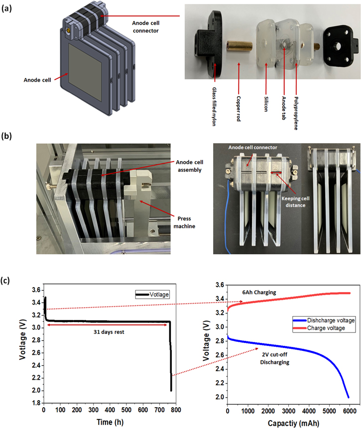
Figure 2. (a) Anode cell connector design for connection structure, (b) Press connecting method using press machine and structure of anode cell module, (c) Water-proof test of anode cell connector: After 6Ah charging the 4 Parallel SWB module, rest in salt-water for 31 d, and discharge with the 2 V cut-off discharge.
Download figure:
Standard image High-resolution imageTo find the optimal cathode current collector arrangement, the anode cell was stacked at a uniform distance, and the current imbalance between anode cells was observed according to the three types of arrangement (Fig. 3a). In Case 1, the cathode current collector was placed on one side of the stacked anode cell; in Case 2, it was placed around the stacked anode cell; and in Case 3, it was placed between each anode cell. When charging with 450 mA, in Case 1, cell 1: 84 mA, cell 2: 119 mA, cell 3: 247 mA, showing a maximum current deviation of 163 mA. In Case 2, the same current which is 160 mA flowed in cell 1 and cell 3, but cell 2 was 140 mA. In Case 3, all cells have same current distribution, 150 mA (Fig. 3b). Because current imbalance between cells in a battery module reduces their cycle life in parallel connection, 15,26 Case 3, with the smallest current imbalance, was determined to be the optimal arrangement.

Figure 3. (a) Three case of cathode current collector arrangement, (b) comparison of current imbalance according to arrangement of cathode current collector.
Download figure:
Standard image High-resolution imageCycle life test of 1S 5P SWB module
The cycle life test of the 5P SWB module was conducted using a 1Ah SWB unit cell. Cycle life test at 0.2 C-rate showed a cycle lives of 145 for the 5P SWB module (Fig. 4b). This cycle life is approximately 63% less than the 390cycles of a unit cell (Fig. 4a). Cell deviation might be what causes the module's cycle life to be reduced. The three major causes of this cell deviation are as follows: 1. non-uniformity in cell production; 2. non-uniformity in cell assembly; and 3. Parameter variables in operating parameters. 17,27 To begin, it is difficult to manufacture homogeneous cells because all SWB prismatic cells are made by hand. Second, cell deviation occurred as a result of the inability of the contact resistance generated during cell assembly to be uniform. Finally, local variations in salinity and temperature may occur while the module is operating. However, a detailed analysis will be required to ascertain which of the primary reasons and how to mitigate them. This requires further research in order to develop a SWB module with a long cycle life.

Figure 4. Cycle life test of (a) unit cell, (b) 5 parallel module; 1Ah SWB unit cell is used and experimental condition is DoD 100% with 0.2C-rate.
Download figure:
Standard image High-resolution image5S 4P module design and electrochemical performance
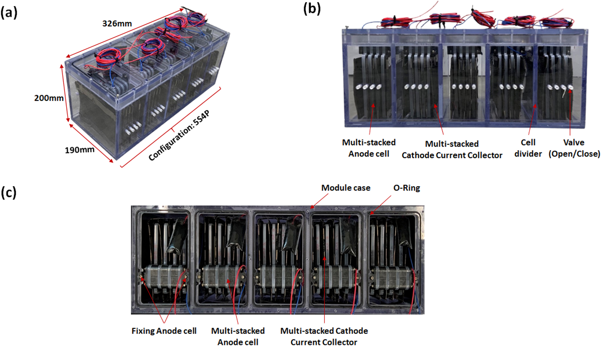
After dividing the module case into five zones to accommodate the 5S connection, each zone was filled with a 4P module to create a 5S 4P module. The 5S 4P module was designed to be 190 × 326 × 200 mm, considering the anode cell size of 136 × 6.3 × 170 mm, frame thickness of 10 mm, cell-to-cell distance of 7 mm, and the volume of connection materials (Fig. 5a). On the side plate of the module casing, a valve was fitted to permit both open and closed systems (Fig. 5b); Leakage should not occur in a closed system, which is why it was packed with a Nitrile-Butadiene Rubber (NBR) O-ring and seawater-resistant SUS 316 bolts (Fig. 5c). Additionally, the module case structure stabilized the stacked anode cells to prevent them from being shook by vibration. When SWB cells are stacked, the distance between the anode cell and the cathode current collector was not carefully considered because when the cathode current collector is attached to the anode cell and separated from the anode cell, there's no big performance difference.

Figure 5. Structure of 5S 4P seawater battery module: (a) overall view, (b) front view, (c) top view.
Download figure:
Standard image High-resolution imageTo quantitatively evaluate the performance of the 5S 4P module, the discharge energy and power of the unit cell and module were compared. A unit cell with 1.5Ah capacity was charged and discharged at a 0.1 C-rate. In the fifth cycle, the discharge energy was 3.92 Wh (Fig. 6a). The 5S 4P module was also charged and discharged 6 Ah (1.5 Ah Cell−1) at 0.1 C-rate. The the discharge energy was 77.88 Wh, which is 19.87 times that of a unit cell (Fig. 6b). When twenty cells are stacked, they should theoretically have twenty times the energy of a unit cell. As a result of the experiment, stacking 20 cells results in nearly little energy loss. However, it suffered a significant decline in power performance. At 20 °C, unit cells of SOC 20, 40, 60, and 80% achieved discharge powers of 1.94. 2.02, 2.04, and 2.11 W, respectively (Fig. 6c), while the 5S 4P modules recorded 24.37, 24.98, 25.5, and 26.22 W, respectively, which are approximately 12.5 times higher than the corresponding unit cell power (Fig. 6d). For charge power, unit cells with SOC of 20, 40, 60, and 80% achieved 2.65. 2.59, 2.5, and 2.46 W (Fig. 6c) while the and 5S 4P modules recorded 30.84, 30.23, 28.73, and 26.67 W, respectively (Fig. 6d), which are approximately 11.6 times higher than the corresponding unit cell power. As a result, power did not rise in multiples of the number of stacked cells. A power loss of roughly 37.5 percent was observed as compared to the theoretical value in the twenty-cell stacked module. The cause of power loss is most likely contact resistance, as resistance increases by 0.577 after the 5S 4P connection (See Table I). When resistance is increased to 0.577, approximately 26.7 percent of power is lost in comparison to theory. As a result, research into contact resistance reduction for high-power modules should be expanded.
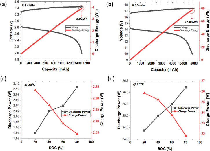
Figure 6. Charge/discharge profile of closed-type SWB (a) unit cell, (b) 5S 4P module, Power test results for different SOCs (c) unit cell, (d) 5S 4P module.
Download figure:
Standard image High-resolution imageMarine application: light buoy
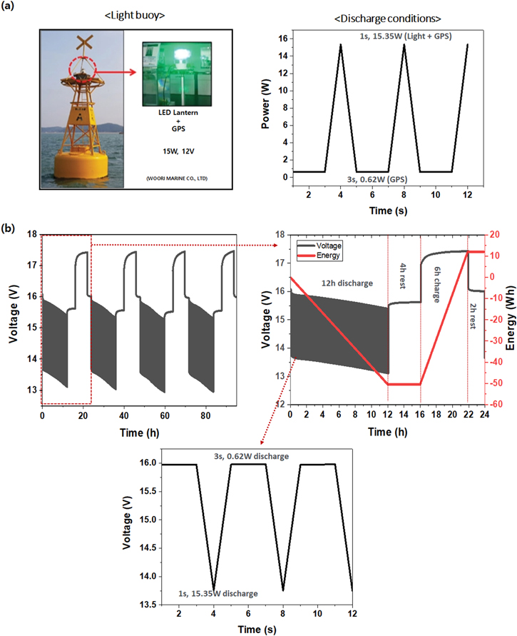
In addition, a test was conducted with the 5S 4P module according to the actual operating conditions of the light buoy, which is a marine application. A light buoy is a structure that floats on the sea to inform sailing ships of obstacles such as reefs or to indicate routes by illuminating. The light buoy in this work required an operating voltage of 12 V and an output of 15 W. It was driven by discharging for 12 h from 6 PM–6 AM and charging via a solar panel from 10 AM–4 PM. The discharge condition was a pulse output of 15 W to operate the lighting and global positioning system (GPS) together for 1 s, and when the lights are turned off, only GPS for 3 s at 0.62 W (Fig. 7a). The test was performed in the order of 12 h of discharging under the light buoy discharge condition, 4 h of rest, 6 h of charging with 625 mA (constant current mode), and 2 h of rest. The test determined that, when discharging 15 W, the operating voltage of 5S 4P module was maintained at 12.9–13.1 V and the discharge current was 1.15–1.16 A. When only the GPS was used, the operating voltage was 15.3–15.4 V and the discharge current was 40.3–40.5 mA. As a result of discharging for 12 h a day, an average of 50 Wh per day was consumed as discharge energy (Fig. 7b). This experiment confirmed that the 5S 4P module with 78.88 Wh and 24.37–26.2 W could operate the light buoy. But in order to actually use the battery on the light buoy, it must also have energy in consideration for situations in which solar power cannot be used for up to 7 days due to bad weather. Therefore, for practical applications, additional research is needed to increase the energy density.
Figure 7. (a) Picture and discharging conditions of light buoy, (b) performance of 5S 4P module with light buoy driving conditions.
Download figure:
Standard image High-resolution image
Conclusions
In order to expand the application range of SWBs, the SWB module with high operating voltage and high power was demonstrated. In this paper, the following three studies were conducted: (1) Design anode cells connectors with water-proof function for prevent short-circuit, (2) Arrangement of cathode current collector for minimizing current imbalance, (3) 5 Series 4 Parallel module design tested for 12 V, 15 W applications. As a result, the new anode cell connector was designed with water-proof function for prevent short-circuit. In addition, to minimize current imbalance, the arrangement of cathode current collector was compared. Based on these designs, the cycle lives of 145 cycles in 5 parallel SWB module was achieved. Through the fabrication of 5S 4P SWB module and performance evaluation, 77.88 Wh and 24.2–26.2 W were recorded, showing an increase in energy of 19.87 times and an increase of power by 11.5 times compared to a unit cell. Additionally, the applicability of SWB to a marine equipment is confirmed through the test under operating conditions of light buoy.
This study provides the groundwork for future research on SWB modules. In the future, it will be important to thoroughly analyze the causes of cell deviations in SWBs to enhance the cycle life of module. Additionally, further research on material and design in module should be performed to enhance the energy density and power density, which is essential to expansion of SWBs area.
Acknowledgments
This study was supported by the Korea Institute of Energy Technology Evaluation and Planning (KETEP) grant funded by the MOTIE (20215610100040, Development of 20 Wh seawater secondary battery unit cell and also supported by the National Research Foundation of Korea (NRF) grant funded by the Korea government (MSIT) (No. 2020R1A4A1019568).