
Abstract
Iron (Fe)-based layered oxide cathodes that employ Fe3+/Fe4+ redox reaction present a family of attractive cathode materials for sodium-ion batteries as iron is abundant, low-cost, and environmentally benign. However, their electrochemical performance is not yet satisfactory and requires further improvement. In this study, we investigate the effect of electrolytes on the electrochemical performance of α-NaFeO2, a prototypical model of Fe-based layered cathodes. First, we established the critical impact of the poor cathode-electrolyte interfacial stability on cell performances. Systematic electrochemical tests and material characterizations further revealed the degradation mechanism in which the highly reactive Fe4+ state in the charged Na1−xFeO2 electrodes promotes severe electrolyte decomposition and subsequent growth of a thick interface layer that leads to impedance rise and performance degradation. In addition, the superior performance of NaPF6 over NaClO4 and the beneficial effect of the FEC additive are reported.
Export citation and abstract BibTeX RIS
Increasing demand for renewable energy impels the development of large energy storage systems (ESS). With their high energy density and technological maturity, lithium-ion batteries (LIBs) are considered as one of the most practical options for ESS applications. However, it also poses a serious question about the strategies that solely rely on LIBs for the wide deployment of grid-scale ESS as the price of lithium is likely to face a sharp increase throughout the next decade with the rapidly growing electric vehicle sector. 1–3 Sodium-ion batteries (SIBs) can be an attractive low-cost alternative to LIBs because sodium is far more abundant and the similar cell chemistry allows rapid benchmark of existing LIB technologies in commercialization. 4–6 Although the energy density of SIBs is inherently lower than that of LIBs, the performance-cost ratio of the system can be further optimized for ESS applications that have less stringent performance requirements than life cycle cost requirements by constructing the cells only with low-cost, sustainable materials. 7
Transition metal elements comprising the cathode active material account for the largest portion of the total materials cost of battery cells. 8 It is thus imperative to develop sustainable SIB cathodes based on earth-abundant elements such as manganese and iron. Iron in particular is an ideal material in terms of natural abundance, domestic supply chain, and low health and environmental impacts. In this context, olivine LiFePO4 is gaining more traction as a sustainable cathode for LIBs again and SIBs cathodes have also seen progress in the development of Fe-based polyanion structures such as Na2FeP2O7, 9,10 Na4Fe3(PO4)2(P2O7), 11 Na3Fe2(PO4)(P2O7), 12 and NaFePO4F. 13 These polyanion compounds use Fe2+/3+ redox center that is stable but low in average operation voltage. The reversible operation of higher voltage Fe3+/4+ redox is hypothetically possible in lithium transition metal oxides such as LiFeO2 but has not yet been demonstrated because of the chemical instability of Fe4+ state cations and severe cation mixing between Li+ and Fe3+ that are similar in size (rLi+ = 76 pm, rFe3+ = 64.5 pm). 14 On the other hand, the large size difference between Na+ and Fe3+ can alleviate the severe cation mixing (rNa+ = 102 pm) in sodium transition metal oxides. Thus, building on the seminal observations by Kikkawa, et al. in 1985 15 and Takeda, et al. in 1994 16 that the rare oxidation state of Fe4+ is stabilized in desodiated α-Na1−yFeO2 structure, a series of Fe-based layered oxides that operate with reversible Fe3+/4+ redox reaction have been developed as SIB cathodes, such as NaFeO2, 17,18 O3-Na(Fe1/3Mn1/3Ni1/3)O2, 19 and P2-Na2/3(Fe1/2Mn1/2)O2. 20
Nevertheless, the cycle stability of the Fe-based layered oxides is still unsatisfactory and requires further improvement. 21 The gradual performance degradation in layered Nay(Fe1-xMx)O2 cathodes (where M = transition metals) has been largely attributed to the structural and chemical instability of the oxidized cathodes. According to the crystal field theory, Fe3+ has no preference for one site over another between the octahedral and tetrahedral sites in layered oxide structure, and thus can easily migrate from the original octahedral site to the adjacent tetrahedral site in the sodium layers when sodium vacancies are created upon charging, subsequently hindering sodium-ion diffusion. 22 Moreover, Fe4+ in the oxidized cathodes is chemically reactive and can spontaneously reduce to Fe3+ with concomitant electrolyte oxidation. The detrimental chemical reaction between unstable Fe4+ species and the electrolyte leads to the growth of the cathode electrolyte interphase (CEI) layer increasing interfacial impedance. 23
Various cathode optimization strategies such as cation substitutions and structural modifications have been attempted to improve the bulk structural stability of layered NayFe1−xMxO2 cathodes. 21,24–27 However, there are only few reports that address the chemical instability issue. Such insufficient cathode-electrolyte interface engineering in the past development of SIBs is largely ascribable to the lack of battery-grade electrolytes that have been commercially available. For instance, even high-purity NaPF6, which is the salt of choice for state-of-the-art SIB electrolytes, has not been commercially available until very recently, not to mention other kinds of salts. It is noteworthy that even a small concentration of impurity species in the electrolyte can trigger a significant parasitic reaction distorting the performance figure-of-merit evaluation. For this reason, most work on the prototype Fe-based cathode, NaFeO2 in the past decade has been carried out using NaClO4-based electrolytes in spite of their limited oxidative stability and safety concerns, 28–30 and the same is true in our previous study in 2015 that revealed the spontaneous chemical degradation mechanism of charged NaFeO2 cells. 23
Herein, we revisit the chemical instability of charged α-NaFeO2 cathode. Using a battery-grade NaPF6 salt and electrolyte solvents, we evaluate the chemical compatibility of various electrolyte solutions against charged NaFeO2, and show that the proper choice of electrolyte, that forms a more stable cathode-electrolyte interface (CEI) layer, is critical for the performance of Fe-based cathodes.
Experimental Methods
Materials preparation and characterization
For NaFeO2 synthesis, stoichiometric amounts of Na2O2 (Sigma Aldrich, 97%) and Fe3O4 (Sigma Aldrich, 97%) were thoroughly mixed using a high-energy ball milling machine (Spex mill) for 30 min, pressed into a pellet, and heat-treated at 650 °C for 12 h in air. The temperature ramping rate was 3 °C min−1 and the cooling was not controlled. The pellet was transferred to an Ar-filled glove box as soon as the temperature dropped near room temperature and then ground into a fine powder using a mortar and pestle.
Scanning electron microscopy (SEM) analysis of the powder and electrode surface morphology was performed by JEOL JCM-6000 plus. Synchrotron X-ray diffraction (SXRD) patterns of the as-synthesized powder and ex situ electrode samples (sealed with Kapton tape) were obtained at beamline 11-ID-C of the Advanced Photon Source (APS), Argonne National Laboratory (calibrated wavelength = 0.1173 Å). The two-dimensional diffraction ring patterns were obtained in transmission mode and integrated into conventional one-dimensional data using GSAS II software. X-ray photoelectron spectroscopy (XPS) analysis was performed with a PHI 5000 VersaProbe II System (Physical Electronics). Samples were transferred without air exposure to an argon-atmosphere glovebox connected to the XPS system. The spectra were collected using an Al-Kα radiation (hν = 1486.6 eV) beam (100 μm, 25 W), Ar+ and electron beam sample neutralization, in Fixed Analyzer Transmission mode. Peak fitting was processed using Shirley background correction and the Gaussian–Lorentzian curve synthesis available in MultiPack software. XPS spectra were aligned to the carbon black component in the C1s spectra at 284.8 eV.
Electrochemical tests
Electrochemical tests of NaFeO2 were performed using 2032-type coin cells. The electrode slurry was prepared by mixing the cathode active material, super P carbon (C45, Timcal), and polyvinylidene fluoride (Solvay) binder in 80:10:10 wt% ratio and dispersing in N-methyl-2-pyrrolidone using a high-shear mixer (Thinky, ARE −310). The slurry was cast on an aluminum foil current collector and the electrode was dried in a convection oven and a vacuum oven at 75 °C overnight. The typical cathode active material loading was ∼4 mg cm−2. The electrolytes were prepared by dissolving 1 M concentration of NaPF6 (Stella Chemifa, 98%, Japan) or NaClO4 (Sigma Aldrich, ≥98%) salt in propylene carbonate (PC, Sigma Aldrich, 99.7%) or ethylene carbonate/diethyl carbonate mixture solvent (EC/DEC, 1:1 mixture, Sigma Aldrich, ≥99%). Fluoroethylene carbonate (FEC, Sigma Aldrich, ≥99%) was used as an electrolyte additive (2 wt%). A glass fiber filter (Whatman, F grade) was used as a separator and a sodium metal disc was used as a counter electrode. Coin cells were assembled in an argon-filled glove box. The galvanostatic charge-discharge cycling tests were performed by a battery cycler system (MACCOR) connected to a coin cell climate chamber, which was set at 30 °C. Chronoamperometry tests were performed to demonstrate the leakage current. The NaFeO2 cell was charged to 3.8 V and the constant voltage of 3.8 V was maintained for 10 h. And the corresponding current value was monitored. Electrochemical impedance spectroscopy (EIS) was measured using a three-electrode coin cell in a frequency range from 200 kHz to 10 mHz by a potentiostat (VSP-300, Biologic). The three-electrode coin cell (2032-type) was fabricated by adding a Na metal reference electrode with Cu wire between the cathode and anode electrodes.
Results and Discussion
Preliminary electrochemical performance screening
A phase-pure α-NaFeO2 (denoted as NFO hereafter) powder was obtained by solid-state synthesis. The XRD and SEM characterization confirmed the layered structure (R-3m, a = 3.0254 Ǻ, c = 16.100 Ǻ) and random granular particle morphology of the sample (Fig. S1a (available online at stacks.iop.org/JES/169/030536/mmedia)). The coin cell tests performed with the 1 M NaClO4 in PC baseline electrolyte (denoted as NaClO4-PC hereafter, Fig. S1b) showed the expected electrochemical properties as reported in the literature (Table SI). 23 NaClO4 has been commonly used in the lab-scale research since it is cheap, easy to handle and stable to hydrolysis (relative to fluoro-type salts). However, its practical use is limited due to its explosive nature and limited electrochemical stability. On the other hand, NaPF6 has higher ionic conductivity and a wider electrochemical stability window than NaClO4. With the increasing interest in SIBs, battery-grade NaPF6 has become commercially available very recently. For electrolyte solvents, carbonate-based solvents are preferred because their high dielectric constant and low viscosity provide a good basis for sufficient salt solubility and ionic conductivity. While EC-based mixture solvents form a good solid-electrolyte-interface (SEI) layer on the electrode surface, PC has a low melting temperature (Tm = −48.8 °C) providing good low-temperature performance (See Table SIII for the physicochemical properties of several electrolytes). With this information at hand, the baseline NaClO4-PC performance was compared to the 1 M NaPF6 in PC (i.e., NaPF6-PC) and 1 M NaPF6 in EC/DEC (i.e., NaPF6-EC/DEC) electrolyte data (Fig. S1c). Note that the battery-grade NaPF6 used in this study was dissolved completely in the electrolyte solvents, unlike other low-purity NaPF6 salts which leave undissolved residue impurities when 1 M salt is dissolved. While the three electrolytes mark almost the same initial discharge capacities, the initial coulombic efficiency (ICE) and capacity retention improve with the NaPF6-based electrolytes. (Fig. S1d). The effect of solvent choice between PC and EC/DEC was not significant when NaPF6 was used. Therefore, the solvent will be fixed to PC hereinafter, and the following discussion will focus on the effect of salts and the FEC additive.
Comparison of electrolyte salts (NaClO4 vs NaPF6)
As briefly described above, Fig. 1 shows the improved electrochemical performance for the NaPF6-PC cell in comparison to that of the baseline NaClO4-PC cell (v = 2.0–3.8 V vs Na, i = 10 mAh g−1). While the initial discharge capacities are identical, NaPF6-PC has three times better capacity retention than NaClO4-PC after 10 cycles and greatly improved ICE. This result indicates that the large 1st cycle irreversible capacity loss of the NaClO4-PC cell is due to the poor electrolyte stability. To amplify the detrimental effects of chemically reactive Fe4+ state against electrolytes, an aging cycle test was carried out using the following protocol (v = 2–3.8 V vs Na, i = 10 mA g−1): charging (C1)—aging for 10 d at open circuit condition (aging@SOC (state-of-charge))—discharging (D'1)—charging (C'2)—discharging (D'2). In Fig. 1b, the discharge capacity of the NaClO4-PC cell significantly decreases after the aging@SOC step (D1 = 98 mAh/g vs D'1 = 40 mAh g−1). The subsequent C'2 and D'2 capacities show even lower values indicating an irrecoverable degradation to the cell. The NaPF6-PC cell also shows a similar decrease in discharge capacity after aging (Fig. 1c; D1 = 98 mA g−1 vs D'1 = 43 mAh g−1), however, the average voltage of the D'1 discharge is higher than that for NaClO4-PC, and more interestingly, the performance is partially recovered in the subsequent charge and discharge cycle (D'2 = 61 mAh g−1).
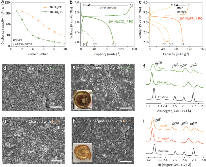
Figure 1. Comparison between NaClO4 and NaPF6 salts (1 M NaClO4 in PC vs 1 M NaPF6 in PC): (a) cycle performance of NaFeO2 cathode cycled between 2 and 3.8 V at 10 mA g−1; (b), (c) initial voltage profiles of NaFeO2 cathode cycled with 1 M NaClO4 in PC (b) and 1 M NaPF6 in PC (c). The solid line and dotted lines represent, respectively, continuous cycling (C1–D1) and aging cycling (C1-aging-D'1-C'2-D'2) conditions; (d), (e), (g), (h) SEM image of charged NaFeO2 electrodes before and after the aging step (inset image: glass fiber separator after aging). The scale bar is 10 μm; (f), (i) Synchrotron XRD patterns of the pristine, charged, and aged electrodes.
Download figure:
Standard image High-resolution imageConsidering the highly oxidative Fe4+ species in charged NFO surface, 23,31 it can be postulated that both electrolytes experience a significant oxidative decomposition during the aging@SOC step. This was corroborated by the SEM images of the aged electrodes that revealed the formation of thick CEI layers, a product of electrolyte decomposition (See Figs. S2 and 1d, 1e, 1g, 1h). NaPF6-PC (Figs. 1g, 1h) built a relatively thinner CEI layer than NaClO4-PC (Figs. 1d, 1e), indicating the better cathode-electrolyte interfacial stability of NaPF6. Moreover, we've also found that the aging cycle significantly damages the glass fiber separator (see insets in Figs. 1e, 1h); the white glass fiber turned dark brown after the aging step. The discoloration can be attributed to iron dissolution from the charged NFO cathode. 32 The separator extracted from the NaPF6-PC cell herein again shows relatively milder discoloration. These observations correspond well with the electrochemical test results, and as such establish a good correlation between electrolyte stability and NFO cell performance.
The bulk structural damages made to the layered NFO cathode during the aging period were evaluated by ex situ synchrotron XRD. In Figs. 1f, 1i, the as-charged electrodes (C1) present typical peak shifts corresponding to sodium deintercation from the layered structure: c-axis expansion and a-axis contraction. 22,23 The percent expansions in the c-axis parameter were 1.7% and 1.5% for the electrodes cycled in NaClO4-PC and NaPF6-PC, respectively. The virtually identical values indicate the similar amounts of actual sodium ions deintercalated from the NFO structure in both cells although the NaClO4-PC cell marked higher initial charge capacity due to severe parasitic electrolyte decomposition. After the aging step, however, the ex situ XRD patterns show different bulk structural degradation modes depending on the electrolyte used. For the XRD pattern aged in NaClO4-PC shown in Fig. 1f, the (003) and (006) are shifted and broadened toward a higher 2θ angle (Δ2θ(003) = 0.003°–0.012°). The broadened peaks are not symmetrical and can be deconvoluted into multiple peaks having smaller c-axis parameters than the as-charged value. The (101) and (012) peaks also moved to a lower angle toward stochiometric NFO. These results are associated with the self-discharging behavior by sodium re-insertion into the bulk Na1-xFeO2 when aged at SOC. On the other hand, the NFO electrode aged in NaPF6-PC exhibited less severe structural degradation; in Fig. 1i, the (003) and (006) peaks remain symmetrical and the peak shift is smaller than that for the NaClO4-PC case (Δ2θ(003) = 0.002°) suggesting less amount of sodium re-insertion and reduced self-discharging. It should, however, be noted that the high-purity NaPF6-PC electrolyte alone didn't perfectly stabilize the cathode-electrolyte interface and the as-charged Na1−xFeO2 phase as evident in the apparent broadening of the (101) and (012) peaks toward the lower 2θ angle. Nevertheless, the results in this section provide compelling evidence that the electrolyte salt significantly affects the electrochemical performance of the NFO cathode. The results obtained here are in good agreement with previous simulation data that PC-PF6 − has a higher oxidative decomposition potential than PC-ClO4 −. 33 Also, it has been reported that the decomposition products of NaPF6 (e.g., NaF) are more Na-conductive than those of NaClO4 (e.g., NaCl, NaClOx) resulting in a thinner SEI layer and a lower interfacial resistance. 34
Effect of FEC additive in cathode-electrolyte interface
Building on the improved NFO performance with the battery-grade NaPF6 salt, we have further investigated the effect of fluoroethylene carbonate (FEC) additive, which has been reported to improve the electrode-electrolyte interface properties by forming a fluorine-incorporated stable solid-electrolyte interface layer. 35–37 Figure 2a presents the voltage profiles of the NFO electrode cycled in the NaPF6-PC electrolyte containing 2 wt% FEC (NaPF6-PC-FEC). The FEC addition further improved the ICE value from 83% for the FEC-free cell to 93%. The capacity retention (after 10 cycles) was also enhanced from 27% to 54% with FEC (Fig. S3). To the best of our knowledge, the ICE and capacity retention values reported here are the best among previously reported NFO performances (Table SI).

Figure 2. Effect of the FEC additive on the electrochemical properties of α-NaFeO2 cell (1 M NaPF6 in PC (yellow plots) vs 1 M NaPF6 in PC with 2% FEC (blue plots): (a) Initial voltage profiles; (b) comparison of cycle performance after aging steps; (c) chronoamperometric profile at a constant voltage of 3.8 V vs Na; (d), (e) Evolution of electrochemical impedance spectra (EIS) of charged NaFeO2 electrodes as a function of aging time (three-electrode cell).
Download figure:
Standard image High-resolution imageThe stabilizing effect of FEC was better demonstrated when the NFO electrode was held at a charged state. In the aging cycle test, the D'1 discharge capacity obtained after the aging@SOC step reached up to 90% of the D1 discharge capacity (D1 = 101 mAh g−1 vs D'1 = 91 mAh g−1). This is a dramatic improvement when it is considered that the D'1 discharge capacity for the FEC-free NaPF6-PC electrolyte cell was only 40% of the D1 capacity. In addition, compared to FEC-free electrolytes in which the discharge capacity rapidly decays after aging, the aging@SOC step didn't affect the following cycle performance when the FEC additive was used (Figs. 2b, S3c). Also, chronoamperometry was performed to obtain the leakage current as an indicator for measuring side reactions at the electrode-electrolyte interface. Figure 2c exhibits approximately four times higher leakage current for the FEC-free electrolyte cell than that for the FEC-containing cell, further supporting the benefit of FEC additive in suppressing the parasitic side reaction. These electrochemical test results suggest that FEC helps form a more stable interface on the charged Na1−xFeO2 electrode, leading to improved electrochemical stability.
One may wonder at this point whether the improvement on the half-cell performances with FEC additive is rather due to the improved interface on the Na metal anode than on the cathode. Therefore, a three-electrode coin cell with a reference electrode was configured (Fig. S4) to separate the cathode-electrolyte interaction from the Na metal contribution. In the electrochemical impedance spectroscopy (EIS) test, the three-electrode coin cell was charged up to 3.8 V vs Na and aged while collecting the impedance data as a function of aging time. Figures 2d, 2e display Nyquist plots that were collected as a function of aging time. The EIS data were analyzed using the equivalent circuit shown in Fig. S5 and the internal resistance values were obtained. The initial internal resistance for the FEC-free sample (1.9 kΩ) is slightly higher than that for the FEC-containing electrolyte sample (1.5 kΩ). During the subsequent aging, a striking contrast in the impedance behavior was observed; while the total cathode-electrolyte interfacial resistance for the NaPF6-PC cell increased more than 10 times higher (22 kΩ) after aging, the FEC containing cell showed only 1.5 times increase (2.3 kΩ). The EIS results obtained with the 3-electrode cells provide compelling evidence that the battery-grade NaPF6-PC electrolyte is still prone to continuous electrolyte decomposition with the concomitant formation of unfavorable surface product layer on the charged NFO surface, and that FEC additive can effectively suppress it.
In Figs. 3a, 3b, the SEM analysis presents the well-preserved cathode surface morphology for the NFO electrode aged at SOC in NaPF6-PC-FEC. The electrode aged with FEC shows a more uniform and thinner surface CEI morphology compared to the FEC-free samples discussed in the previous section. And as seen in the inset image, the clean separator collected from the FEC-containing cell contrasts with the significantly discolored separators harvested from FEC-free cells indicating significantly suppressed iron dissolution with the 2% FEC addition. With such improved cathode-electrolyte interfacial stability, the charged Na1−xFeO2 structure also maintained the as-charged layered structure better, as evidenced by the corresponding ex situ XRD pattern in Fig. 3c that shows negligible peak shifts (Δ2θ(003) = 0°) and broadening.

Figure 3. Effect of FEC on the cathode-electrolyte interface stability (1 M NaPF6 in PC vs 1 M NaPF6 in PC with 2% FEC): (a), (b) SEM image of NFO electrodes before and after aging at charged state. The scale bar is 10 μm; (c) Synchrotron XRD patterns of pristine, charged, and aged electrodes; (d)–(e) O1s and (f), (g) F1s XPS analysis of charged and aged electrodes.
Download figure:
Standard image High-resolution imageThe chemical species in the CEI layers were investigated by XPS on the charged and aged electrodes with NaPF6-PC and NaPF6-PC-FEC electrolytes. Figures 3d, 3e display the XPS spectrum of O1s region. The main peaks observed in O1s were at 533.3 eV and 531 eV, assigned to C–O and C=O, repectively. Those peaks are known to be from sodium alkyl carbonate which is the result of electrolyte decomposition. 38 A peak at 529.8 eV is due to the M–O signal from the lattice oxygen in NFO and a peak at 537 eV is from Na KLL auger. With FEC additive in the electrolyte, relatively lower intensities for the C–O and C=O components were observed for both charged and aged status comnpared to FEC-free electrodes. This is consistent with the results shown in electrochemical testing (Fig. 2) and the SEM analysis results (Fig. 3b). FEC additive participates to form an effective passivation layer on the NFO surface and suppress the continuous side reaction between charged NFO and electrolyte, resulting in improved electrochemical performance.
While the C–O and C=O signals in the O1s spectra give organic products related information, the F1s spectra can provide information regarding inorganic products in a CEI layer. In Figs. 3f, 3g, a peak at 685 eV and 688.21 eV corresponds to the Na–F and C–F (PVDF), respectively. The peak intensities for Na–F in both FEC-free and FEC-added samples are similar at charged condition (see Table SII). Unlike the organic products in O1s spectra, the greater intensity rise after aging@SOC step was observed for Na–F component in the FEC-containing samples. Given that electrochemical performance of NFO was well stabilized with FEC added electrolylte, it can be postulated that the F-containing inorganic component has an important role in stabilizing the CEI layer on the NFO surface.
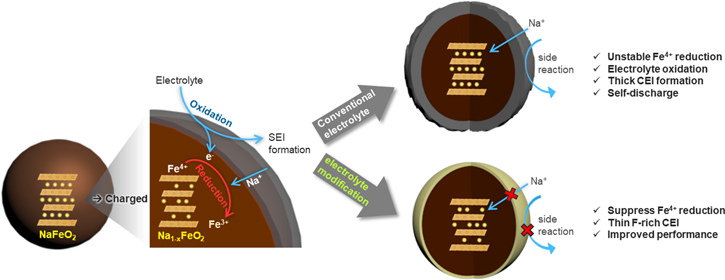
Figure 4 schematically summarizes the effect of electrolyte compositions on the interfacial stability of the charged NFO electrode. When the NFO electrode is charged, the Fe4+ state that is inherently unstable in oxides is generated. With its strong chemical driving force, to be reduced back to a stable Fe3+ state, the Fe4+ species chemically oxidizes electrolyte resulting in self-discharging (sodium re-insertion and Fe4+ reduction) and thick CEI layer formation. The former is recoverable, at least partially, but the latter makes more permanent damage to the cell by continuously increasing the cell impedance. This can be effectively addressed by the electrolyte modified with high-purity NaPF6 salt and FEC additive. The optimized electrolyte produces a more stable CEI layer and significantly improves the electrochemical performance of the NFO cathode.
Figure 4. Schematic diagram of interfacial degradation mechanism of charged Na1−xFeO2 cathode. The highly reactive Fe4+ accelerates the oxidative decomposition of electrolytes at the cathode-electrolyte interface. High-purity NaPF6 salt and FEC additive produce a thinner and more stable CEI layer improving the interfacial stability and cell performance.
Download figure:
Standard image High-resolution image
Conclusions
We have demonstrated that the performance of α-NaFeO2, which is an important model Fe-based cathode, can be dramatically enhanced by improving the cathode-electrolyte interface stability via simple electrolyte optimization. The superior electrochemical performance of NaPF6 over NaClO4 is correlated with its ability to form a more stable CEI layer that can withstand the strongly oxidizing Fe4+ species in the charged Na1−xFeO2. Various performance tests and characterizations have revealed the additional advantages of FEC additive. FEC promotes the formation of a fluorinated inorganic passivation layer that effectively suppresses undesired side reactions, such as uncontrolled electrolyte decomposition, Fe dissolution, and cathode structural degradation. This study highlights the critical importance of interface engineering in the development of Fe-based cathode systems. We expect this work to open up an entirely new range of electrolyte materials and cathode surface engineering strategies for the high-performance, Fe-based sodium-ion cathodes.
Acknowledgments
Support from the Advanced Battery Materials Research (BMR) Program, in particular David Howell and Tien Duong, of the U.S. Department of Energy (DOE), Office of Energy Efficiency and Renewable Energy, is gratefully acknowledged. The work by K. Ku was supported by the research fund of Hanbat National University in 2021. The work by Y. Kim was supported by the 2021 Research Fund (1.210041.01) of UNIST (Ulsan National Institute of Science & Technology). The submitted manuscript has been created by UChicago Argonne, LLC, Operator of Argonne National Laboratory ("Argonne"). Argonne, a U.S. Department of Energy Office of Science Laboratory, is operated under Contract No. DE-AC02-06CH11357. The U.S. Government retains for itself, and others acting on its behalf, a paid-up nonexclusive, irrevocable worldwide license in said article to reproduce, prepare derivative works, distribute copies to the public, and perform publ.